

A practical framework for teams ready to automate with intent
If you’re building a modern assembly line, this isn’t about bolt‑on gadgets — it’s a deliberate systems project. Start with the physics: ultrafast precision matters, and that’s why teams are evaluating femtosecond lasers alongside fiber cleaning heads for repeatable, non‑thermal surface preparation. The Framework approach below breaks the integration into clear stages — requirements, hardware, control, validation — so engineers and production leads can align on throughput, cycle time, and quality from day one. Industrial hubs from Stuttgart to Munich — classic Industry 4.0 examples — have driven these approaches into mainstream practice, which should tell you this is proven, not theoretical.
Stage 1 — Define the problem and success metrics
Be ruthless about what “clean” means for your part and process. Is the goal oxide removal, adhesive residue clearance, or micro‑contaminant ablation? Specify measurable outcomes: acceptable surface roughness (Ra), residue thresholds, and allowable cycle time per part. Include constraints such as part fixturing, access angles, and acceptable thermal diffusion to avoid distortion. Getting these specs right upfront prevents later fights over tolerances and throughput.
Stage 2 — Hardware architecture and core components
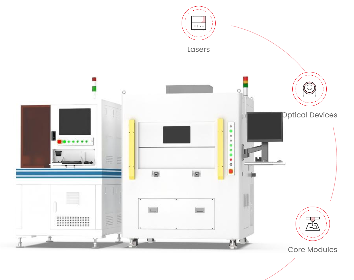
Design around reliable elements: a fiber‑delivered laser source, beam delivery and focusing optics, a scanning head or galvo system, and a robotic end‑effector. Key terms to match to your spec: laser fluence, spot size, and pulse duration. Fiber lasers give robustness; pair them with controlled beam delivery to manage spot size and avoid substrate damage. For sub‑micron contaminants or delicate coatings, consider ultrafast options or hybrid setups that combine fiber laser power with short pulse regimes.
Stage 3 — Motion, timing, and controls
Integration fails when timing is hand‑waved. Sync the laser fire with robot pose and conveyor indexing. Use hardware interrupts or EtherCAT I/O for deterministic coordination. Implement cycle buffering so the robot doesn’t idle while the laser completes a nested pass. And don’t forget software: your PLC and robot program must include safe interlocks, laser enable lines, and clear error states that map to operator actions — otherwise, small faults become line‑stopping incidents.
Safety and compliance — non‑negotiable basics
Laser safety class, beam enclosures, interlocked doors, and appropriate eyewear are table stakes. Add particulate extraction if the process generates fumes from ablation. Ensure your machine safety file aligns with local regulations and that lockout procedures include laser subsystems. This is not optional — regulatory issues shut lines fast, and reputational damage is real.
Validation, process windows, and ramp strategy
Run Design of Experiments (DoE) to map process windows: vary pulse energy, repetition rate, traverse speed, and standoff distance. Track defect rate, cycle time, and micrograph results. For traceability, log laser parameters (pulse energy, repetition rate) alongside robot pose data per part. If you’re dealing with critical microstructures, consider a pilot with controlled sensors to verify that thermal diffusion and substrate metallography remain within spec — and then scale. —
Common mistakes teams make (and how to avoid them)
1) Treating laser heads as interchangeable. They aren’t — beam profile and focus depth change outcomes. 2) Underestimating fixturing complexity. Small misalignments multiply process variability. 3) Skipping real‑world trials on production fixtures. Lab success doesn’t guarantee line performance. Mitigation: start with a short pilot on your actual tooling, capture data, and iterate quickly.
How femtosecond laser micromachining fits the playbook
When parts demand ultra‑low heat input and micron‑level precision, integrate femtosecond laser micromachining modules into the architecture above. Their extremely short pulse duration minimizes thermal diffusion and collateral damage, enabling precision cleaning of sensitive coatings, micro‑features, or bonded assemblies. Use them where spot size and minimal heat‑affected zones are non‑negotiable — but balance cost and cycle time against those benefits.
Pilot checklist — get your first 90 days right
– Define acceptance criteria and measurement methods. – Lock fixtures and part tolerances. – Run DoE and capture laser fluence and spot‑size data. – Integrate safety interlocks and document SOPs. – Train operators on both robot and laser emergency procedures.
Advisory: three golden evaluation metrics
1) Process Stability Index — measure variance in defect rate per 1,000 parts; target single‑digit percent variance before production scale. 2) True Cycle Time Impact — measure end‑to‑end time added by cleaning, including robot repositioning; aim to keep added time within your takt target. 3) Mean Time Between Adjustments (MTBA) — track how often beam or fixturing tweaks are required; low MTBA signals a robust integration.
Follow those metrics and you’ll make design decisions that matter — not just choices that sound good in a meeting. The right laser‑robot partnership is practical, measured, and repeatable. JPT. —